VLT (Virtual Link Trunking) is a Dell Networking proprietary protocol. This article describes the working functionality of VRRP and Peer-routing when implemented over VLT. For detail configuration I would suggest you to refer the Dell Networking Configuration guide for OS9 platforms.
What is Dell Networking VLT (Virtual Link Trunking)?
In simplified words, a VLT domain is comprised of two Dell Networking switches running OS9 those are connected to each other using an Ethernet link that is known operationally as a VLT Interconnect (VLTi). This results in a pair of switches that present themselves as a single logical entity to a downstream node that is connected to each peer in the VLT domain. The connection from a downstream node (either a switch or Server) will be a portchannel connecting to both VLT peers. The VLT peers (switches running VLT protocol) synchronize protocol state information, MAC address and ARP tables, between them. All VLANs are also automatically allowed on the VLTi link without any manual intervention.
In this article we will discuss about VLT Peer-routing and its advantages over VRRP.
The First hop router redundancy protocol (FHRP) is implemented at the Layer2 & layer3 boundary. We need redundancy for first hop router because, if the first hop router fails, the hosts behind one VLAN will fail to reach other hosts in different VLAN. This is achieved by VRRP. Apart from VRRP, Dell Networking OS9 platforms provide another solution called peer-routing when used in VLT domain.
1.Scenario 1 (VRRP):-
Let’s see how VRRP works without VLT.
In a topology where VRRP is running, we need physical IP and virtual IPs for the VLAN instance. The hosts are configured with virtual IP as default gateway and send their packets with destination MAC of VRRP virtual MAC (00:00:5e:00:01:XX). Only VRRP master controls this MAC and the packets destined to this MAC or the VRRP virtual IP will be forwarded towards VRRP master device. VRRP Backup device only works as standby keeping track of VRRP Master and only actively processes/routes the packet when the active Master fails. In this scenario we are not utilizing the CPU of the VRRP Backup device.
VRRP can only supports up to 255 VLAN instances.
All end hosts use the VRRP virtual IP as their default-gateway. When a Host wants to send a packet out of its network, it will form the packet with Destination MAC as the default-gateway MAC. In this case it will be the VRRP virtual MAC (00:00:5e:00:01:XX).
2.Scenario 2 (VLT+VRRP):-
Now let’s see how VRRP works in conjunction with VLT.
When VRRP and VLT are used in conjunction, both the VLT peers process the packets destined to virtual MAC address.
But frequently the question arises how VRRP Backup actively processes/routes the packets even if the Master is active.
This is achieved as both the VLT peers install the VRRP virtual MAC (00:00:5e:00:01:XX) in their local CAM database as “LOCAL_DA”. This ensures that any packet destined to VRRP virtual MAC will be processed by the peer which received it, rather only the VRRP master in the earlier case (Scenario 1). In other words both VLT peers configured with VRRP act as active forwarders. This ensures that the CPU and other links carrying user traffic are effectively load balanced on both units (VLT peers).
2.1 Sample Configuration

2.2 CAM Table entries
Let’s see the LOCAL_DA entries for VRRP MAC in the CAM tables of VLT peers. I am using the command to get the entry “show cam mac stack-unit 0 port-set 0 | grep 00:00:5e”

In the above output, you can notice the VRRP MAC is installed in the local cam database as ‘LOCAL_DA’ on both VLT peers.
Advantages of Scenario 2:-
Here (VRRP in conjunction with VLT), CPU cycles of both units in VRRP are utilized hence load balancing the user traffic as well as providing the resiliency in the network.
So far we know when VRRP is implemented with VLT, provides a more efficient way of traffic handling topology with effective CPU & Link load balancing as well as resiliency. Then a question arises, how peer-routing is different in achieving these goals and what benefits it offers over VLT+VRRP.
3.Scenario 3 (VLT + Peer-routing):-
Now let’s see how Peer-routing works in conjunction with VLT.
For peer-routing under VLT to be enabled, we need only one command. We don’t need any virtual ip address or vrrp-groups to be configured for each vlans.
Let’s try to achieve the similar resiliency for the default-gateway as we did in scenario 2 but using peer-routing only.
3.1 Sample Configuration
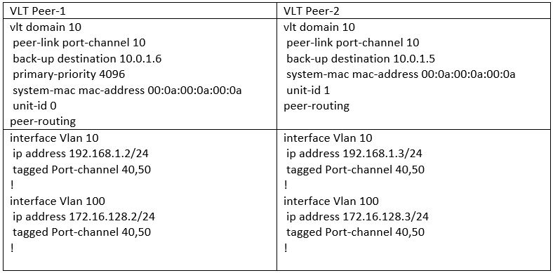
Did you notice that, there is no virtual address under the Layer3 VLANs (SVIs).
If there is no virtual-gateway then what will be the default-gateway configured on the end hosts?
The answer is, you can configure either VLT peer’s IP for that respective vlan as the default-gateway for end host.
For example – If host A is part of vlan 10, then it can have ip address as 192.168.1.x/24, default-gateway 192.168.1.2 or 192.168.1.x/24, default-gateway 192.168.1.3.
3.2 CAM Table Entries
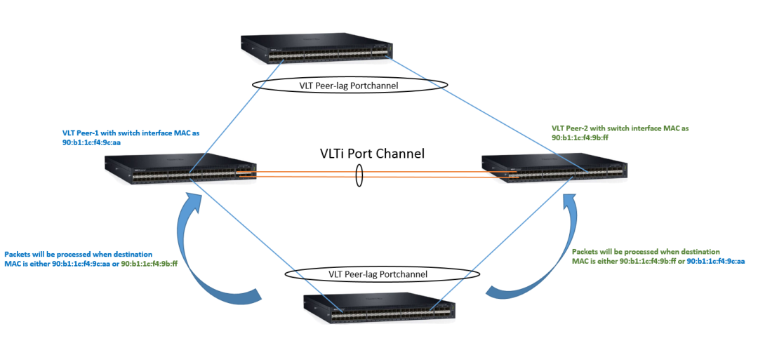
As long as the default-gateway IP belongs to either of the VLT peers, the packet will be processed locally by both.
To know how this happens, we have to look into the CAM table again.

The CAM tables of both VLT Peers are identical and they have installed each other’s MAC under “LOCAL_DA”. Interface 00001 refers to an internal port which leads to CPU. So the CAM entry tells the switch that if any packet reaches it with a destination MAC of either 90:b1:1c:f4:9c:aa or 90:b1:1c:f4:9b:ff , the peer will process the packet and take appropriate action.
Another field is VlanID. Here VlanId shows as “0”. This is a wildcard entry which means the LOCAL_DA values are applicable to all VLANs. Unlike VRRP where there is an entry of Virtual MAC of each VLAN (running VRRP instance), in case of Peer-routing there will be only two entries.
3.3 Benefits of Peer-routing in VLT.
- First Hop router Redundancy
Redundancy is achieved as both the peers independently processes the traffic. If one of the VLT peer fails, other one will take care of the traffic without any user intervention.
- Active – Active routing
Both VLT peers processes the packets actively.
- Less configuration overhead
Unlike VRRP, configuration of extra groups and IP addresses for any Layer3 vlan (SVI) are not required.
- Less use of IP address from the available pool.
Explicitly configuring virtual IP addresses are not needed.
- Occupies less CAM space.
LOCAL_DA entry in CAM will be for the local peer and remote VLT peer only.
- Less CPU intensive
Does not require any additional keep alive packets per VLAN as that of VRRP.
- No scalability limitation on number of VLANs.
VRRP has a limit of 255 groups. But there is no such limitation of Peer-routing.
3.4 FAQ on VLT Peer-routing
i). Does Peer- routing exchange routes with VLT peer?
No, they do not. As described earlier, Peer-routing is a solution for First Hop Router Redundancy. But normally there is a misconception that peer-routing exchanges routes between VLT Peers. This is not true. If any VLT peer has any routes learned via any routing protocol or static routes, those are local to that unit. Peer-routing does not exchange those routes.
If you need to exchange routes between VLT Peers then one has to run any dynamic routing protocol or configure static routes on both the VLT peers for the respective networks.
ii). Can Peer-routing be configured on standalone or stacked units without implementing VLT?
No, it cannot. Peer-routing is a sub configuration under VLT domain configuration. It is a subset of VLT. Hence cannot be configured independently without VLT.
iii). Can VLT Peer-routing and VRRP co-exists inside a network?
Yes, they can. But they are two independent protocols and run separate instances. This is mostly done when a customer is gradually migrating his network from traditional VRRP to Dell VLT solution.
The explanation provided above is my personal understanding of the working of VLT Peer-routing. For more details you can check the configuration guide or with the Dell Networking support.

Hi, I read your post about “VRRP vs Dell VLT Peer-routing”. Would like to express how nice I found it, thank you very much to share. Appreciate if you can comment the following: considering your example, where VLT Peer1 has IP 192.168.1.2 and Peer2 IP 192.168.1.3, and suppose that a Server is configured with Default Gateway 192.168.1.2. Suppose Peer1 failure and Peer2 keep processing traffic from the Server destinated to 192.168.1.2. For the case Peer1 continuous failing and for some reason Peer2 is reloaded. After reloaded, will Peer2 still process packets destinated to IP 192.168.1.2?
I am worried if Peer 2 didn’t keep that information somehow in flash and after reset lose it, and in this case Servers pointing to IP configured on Peer1 will lost connectivity.
LikeLiked by 2 people
Thanks Alaerte for your comments.
There are few enhancements for VLT functionality in the latest 9.11.0.x image. I will check this behavior and respond you back.
LikeLiked by 2 people
It took sometime for me to arrange the boxes to test the scenario.
In the scenario where VLT Peer-1 has permanently failed/removed and Peer-2 is actively doing peer-routing on behalf of Peer-1, upon reload it will no longer do that for peer-1 as it wont sync with Peer-1. Once Peer-1 comes online then both will again sync and become backup for each other.
Let me if you need more info on this.
LikeLiked by 1 person
Great post, up to the point.
Does Peer-Routing handle L3 (non SVI) as well? For example a L3 port-channel in routed mode, not switchport mode.
LikeLiked by 2 people
Hi Raymond,
VLT-peer-link portchannels aka VLT-lag are supported under switchport only.
If it is not a VLT-lag, then the port channel can be a L2 or L3. In that case the entries are local to that particular VLT peer. In the config guide such ports (L2 or L3) are called as orphan ports.
LikeLiked by 2 people
Great post,
If I wanted to span layer 2 across a WAN would that be possible and scal with VLT peer routing
LikeLiked by 2 people
You can not span L2 using VLT alone. If you want to span L2 over WAN , you need to use VXLAN feature.
For example you have two DC and you want to extend the L2 domain between them. In this case you can use VXLAN to extend the L2. VLT can be configured to achieve redundancy at each DC.
LikeLiked by 2 people
Hello,
I am in need a of little guidance, we have primary and back up DCs both running a pair of Dell s4048s configured in VLT/VRRP mode. The DCs are interconnected via a redundant 10G Fiber configured as port channel; so DC1 – VTL sw1 connects to DC2 VLT sw1 and DC1 VLT sw2 connects to DC2 VLT sw2. We don’t have any access layer switches at either site and our servers connect directly to each site’s respective VLTs. in the current config I have successfully extend my L2 accross the 10G fiber and share my IP spaces and vlans across the 2 DCs.
The internet access firewalls (redundant Cisco ASA’s) at each site are attached directly to their respective VLTs, my questions is, what is the best way for me achieve default gateway redundancy? I would like to achieve automatic failure if either site were to lose its internet access. The firewalls and S4048’s do support OSFP which is what I am leaning towards but i am confused as to how I can keep each site’s internet access locally via its respective DIA (Direct Internet Access) and also act as a back for the remote site.
Any help you can provide is much appreciated.
Thank You,
LikeLiked by 1 person
Sorry for late response. I was busy on a new project. Regarding your query, please check the VLT PROXY GATEWAY feature in the Dell networking documents. That will solve your requirement.
LikeLike
Hello,
We are using VLT peer routing + vrrp,
As that any issue,
LikeLiked by 1 person
Hi Damodar,
No both are two different protocols, so there should not be any issue.
Cheers.
LikeLike